West Sea
Company
EVOLUTION OF THE
SEXTANT
By Rod Cardoza
Edited by A. N. Stimson, Head of Navigation
Section, Department of Astronomy and Navigation, National Maritime
Museum, Greenwich, England.
All photographs courtesy West Sea
Company unless otherwise noted
©2000 West Sea Company. All rights reserved. Reproducing any
part of
this article without the expressed written consent of the author
is
forbidden by law. Violators will be prosecuted.
DO YOU HAVE AN INSTRUMENT
YOU WISH TO SELL? WE
BUY!

In modern times the navigator's sextant has become widely
recognized as a universal nautical symbol. Indeed the sextant and the
magnetic compass were the two basic tools of navigation on the high
seas for more than two centuries. Often the mariner's most prized
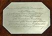
possession was his sextant. Witness the drama evoked by the
handwritten account found with this 19th century English sextant:
|
|
"This sextant was salvaged from the pilot house of the
Norwegian steamship VICTORY by her master, after
being sunk by gunfire from a German submarine 35 miles north
of Ushant at 1:00 PM on July 6, 1917. The master, 2nd mate,
nine crewmen, and a stowaway were rescued from an open boat
by the USS O'Brien at 5:30 A.M. on July 7th, 20 miles
west of Ushant and were later landed at St. Nazaire, France.
As a token of his gratitude for the rescue the master gave
this sextant to the Captain of the O'Brien."
|

|
|
SEXTANT FROM THE SS
VICTORY
|
|
(Private Collection. Ex. West
Sea Co.)
|
It is only in the last 30 years, with
the advent of inertial guidance and satellite
navigation, that the demise of the sextant has
been heralded. Yet, despite its obsolescence in the computer age, the
simplicity, accuracy, and relatively low cost of the sextant will
ensure its survival as a backup navigational tool for years to come.
In tracing the evolution of the sextant and
searching for remaining examples, the first question a collector is
likely to ask is "How old is it?" In attempting to date an early
instrument one must consider the state of communications in the 12th
through the 18th centuries. The word of new inventions and
discoveries was slow to travel. For this reason it was not uncommon
for an innovation to actually be "reinvented" many times over!
Moreover, such was the scientific understanding of the average
Renaissance man that new inventions were often looked upon as
unnecessary complications of methods tried and true. Inertia to
change was great. As recently as 1925 for example, the German
Maritime Ministry, Deutsche Seewarte, was still certifying octants
for use at sea!
Unless an instrument is specifically dated,
the margin of error in dating can be as much as 20 years - more in
older instruments. Bear this in mind as we explore the history of
these fascinating instruments.
The earliest attempt at navigation was
undoubtedly simple coastal piloting. Mariners would venture no
further than the sight of land. The limitations of such navigation
held trade and exploration to a minimum for thousands of years, while
open water sailing was reserved for the incredibly brave or
foolhardy.
The early maritime cultures of the Chinese,
Phoenicians, Polynesians, and Vikings certainly made open ocean
travel a reality. Yet we have no tangible proof of their having used
navigational instruments.
The knowledge required of a mariner in those
instrumentless times was set forth in the Sanskrit Mu'allim of 434
A.D. "He knows the course of the stars, both regular, accidental, and
abnormal, of good and bad weather: he distinguishes regions of the
ocean by the fish, the colour of the sea, the nature of the bottom,
the birds of the mountains, and other indications. And the only aids
he possesseth are his memory, helped by a pilot book, and a sounding
lead or staff."
Quite apart from one another the Chinese,
Egyptians, Babylonians, Greeks, and later the Arabs had discovered
that they could relate their position on the earth relative to the
stars. The observations by their astronomers would give birth to
celestial navigation as it progressed from the 15th century onward.
Simply stated, one's position on earth could be ascertained relative
to a star (fixed point) by measuring the angle of elevation
(altitude) of the star from the observer (apex) and the earth
(horizon).
The earliest practical form of celestial
navigation was probably what was known as "Running Down The Line."
When a ship departed homeport the navigator knew its latitude. At
sea, the navigator could also ascertain his vessel's latitude by
observing the height of Polaris the north star. When it came time to
return to port, the vessel was steered on a northerly or southerly
track until the altitude of Polaris matched that of the homeport.
Then course was altered east or west to "sail down the line" of
latitude. In perfecting this method, the Arabs developed a very
simple device called a Kamal which, by means of a knotted cord,
indicated the height of the pole star at various latitudes. However,
the obvious implications of having to take an indirect course home
stirred navigators and astronomers to find a better way.
During the 15th century the Portuguese began
to explore the west coast of Africa using coastal piloting. As word
of Marco Polo's adventures in China and the treasures of the Orient
spread, ocean travel to India and China demanded improved navigation.
Prince Henry the Navigator founded a navigational school for his
officers where he recruited astronomers, cartographers,
mathematicians, and craftsmen to expand the science of navigation,
construct navigational instruments, and draw up accurate charts.
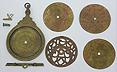
Perhaps the earliest instrument, of which a
rare few still remain, is the astrolabe or "astrolage". The first
astrolabes were non-marine and were constructed in the Islamic
countries of the Middle East which had absorbed and applied the
remnants of Greek science and technology beginning in the 9th century
A.D. The earliest surviving example dates from the 10th century. The
astronomer's astrolabe was a complex and costly affair. In essence it
was a mechanical computer coupled with an alidade mounted on a
two-dimensional planisphere which could be rotated over a plate on
which a network of azimuths and altitudes dividing the heavens were
engraved. Around the rim were scribed the hours of the day, the days
of the year, and the signs of the zodiac. Engraved on the backplate
was even more data.
|

|
|
ASTROLABE
|
ASTROLABE BACK
|
|
Copy of an Islamic astronomical astrolabe showing the
various interchangeable plates for use with differing areas
of the celestial sphere. (Offered by West Sea Co.)
|
A view of the reverse side, clearly showing the signs of
the Zodiac. (Offered by West Sea Co.)
|
The sea astrolabe was an adaptation of the
astronomical type. It was much simplified, as the alidade and degree
scale were really all that was required for the mariner's use. It was
made much heavier to keep it vertical on the rolling platform of a
ship, and cut-out to reduce disturbance in the wind. The sea
astrolabe was introduced about 1460, but did not see general use
until the beginning of the 16th century. Its use persisted until
after 1670, particularly in the fleets of the Spanish and Portuguese,
where it was in evidence early into the 18th century.
For the serious nautical collector the
astrolabe is perhaps the ultimate. Fewer than 100 examples are known
to have survived, and of those most are in poor condition, having
been retrieved from shipwrecks. Obviously one must be extremely
cautious in attempting to acquire an astrolabe. A good many
reproductions, primarily of the astronomical type of these
instruments, were made in the Islamic countries in the late 18th and
19th centuries. More modern reproductions of the sea astrolabe have
also been produced and faked.
A contemporary of the astrolabe, which may
actually have been a predecessor of the sea astrolabe, was the simple
quadrant. Like the sea astrolabe, the mariner's quadrant was adapted
from its earlier and more complex astronomical counterpart. In design
and function it was remarkably simple. It consisted of nothing more
than a triangular plate, the apex of which was fitted with a plumb
bob, with a pair of sighting pinholes on one edge. On the lower limb
a degree scale was scribed, over which the plumb bob swung. In use,
the observer merely lined up the celestial body viewed through the
pinholes then "pinched" the line of the plumb bob on the scale to
ascertain the reading.
Apparently the quadrant was in use well
before 1450, although that was the first recorded mention of the
instrument. Early types were often embellished with the appropriate
landmarks at the point on the scale where their corresponding
readings would fall (e.g., 39 - Lisbon).
The sea quadrant never seemed to gain much
favor with the English sailors, although its use by the Dutch
persisted through the 18th century. Both brass and paper covered
wooden examples survive.

|
|
SIMPLE QUADRANT
|
|
A 17th C. version of a simple quadrant missing its plumb
bob, but with the two sighting pinholes clearly in evidence
at the apex and to the right. This example represents the
late evolutionary period of such instruments. It is engraved
brass whereas earlier versions were of wood and it performs
several functions which the earliest quadrants did not. The
upper portion is engraved with a "shadow square" for use as
a sundial. At the bottom it is divided to single degrees to
allow for sighting the altitude of the sun or stars. Across
the face of the instrument is a depiction of the celestial
hemisphere showing major stars, the Equator, and Tropic of
Cancer. Below these are engraved the months of the year,
accounting for seasonal changes in the sun's declination and
providing a Zodiacal calendar. This form of quadrant was
also known as a "Gunter quadrant" after Edmund Gunter who
described it in 1623. (Private collection)
|
The first real ancestor of the modern-day
sextant as a multipurpose nautical instrument was the cross staff or
Jacob's staff. It was first described in 1342 by a Jewish scholar
named Levi ben Gerson. The instrument, as its predecessors, was an
adaptation from an earlier astronomical surveying device and
performed the same function, albeit with a higher degree of accuracy,
as the Arabian Kamal. In its earliest form the cross staff consisted
of the frame or "staff" and a perpendicular sliding piece called the
"transom" or "cross" (hence the name). By lining up the horizon with
one end of a cross and the celestial object with the other, the
observer had a simple trigonometric computer. Later it evolved into a
more complex instrument consisting of a frame over 30 inches long
with scales engraved on all four sides and two or more transoms.
The cross staff represented a great leap
forward in the art and science of navigation, since it embodied all
of the functions for recording the altitudes of the sun, stars, moon,
and planets, as well as terrestrial sights - a function lacking in
the astrolabe and simple quadrant.
Most frequently the observer's latitude was
found by "shooting" the sun, an expression popularized because of the
resemblance of the instrument to the cross bows of the period. To
this day the navigator's celestial observations are still referred to
as "shots".

|
|
A CROSS STAFF IN USE
|
|
The simplest sight to be taken with a cross staff was for
the observer A, to place the lower limb of the cross on the
horizon B, and the upper limb on the celestial object, C.
The resultant "altitude angle" BAC, was read off of the
divided staff at the intersection of the cross. (From a 16th
C. woodcut)
|
Cross staves were generally constructed of
hardwood (to prevent warping), although an ivory example has been
preserved. Very few have survived even though their use was in
evidence early into the 19th century. Because of their simplistic
design it is likely that most were discarded as useless once they
were brought ashore. When the mariner took his sun shots with cross
staff, the blinding glare of the sun often caused him to turn his
back. By using two crosses and adjusting their angles of incidence,
the observer could sometimes read the shadow cast by the sun on his
instrument. But this procedure was fraught with error. The next
logical step in the evolution of navigation instruments was the
development of the backstaff or Davis quadrant
|
|
|
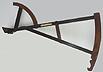
BACKSTAFF
|
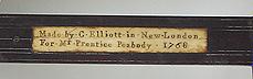
SIGNATURE
|
|
A rare Colonial American backstaff with an ivory maker's
nameplate signed "Made by . C . Eliot . in . New . London .
For . Mr. Prentice Peabody . 1768" The arcs and the
horizon vane are of indigenous American fruitwood (apple or
pear) however the limbs are of ebony indicating that African
trade with the colonies had been established, perhaps via
Britain. (Offered by West Sea Co.)
|
A close-up of the Eliot backstaff nameplate. Note the
unevenness of the signature indicating that Eliot was using
individual letter and number stamps. This confirms the fact
that this was a hand made instrument and that the scale was
laboriously hand-divided. (Offered by West Sea Co.)
|
This ingenious device was first proposed by
English captain John Davis in 1594. The name "quadrant" came from the
fact that 90° (or one quarter of a circle) could be measured
even though there was no full 90° arc on the instrument. The
backstaff consisted of two triangular arcs, the larger of which was
calibrated to 30° and the one at the apex of the instrument
which was calibrated to 60°. In practice the mariner would stand
with his back to the sun. While peering through the sight vane he
aligned the slit in the horizon vane with the horizon and at the same
time adjusted the shadow vane so as to have its shadow fall on the
slit simultaneously. With this ambidextrously accomplished, the sum
of the readings on both arcs indicated the sun's altitude in
degrees.
Most backstaves were of English manufacture,
but American, Dutch and Irish examples do exist. The backstaff gained
rapid popularity after its introduction, particularly with the
English and Dutch sailors. Much care was lavished on its construction
in order to avoid warping and to ensure the accuracy of its scales.
Early instruments were constructed of walnut, lignin vitae, and
fruitwood and were characterized by in-line scales. Later models
included ebony and even mahogany in their construction and featured
diagonal, interpolative scales.
But backstaves were only usable when the sun
was visible, limiting that form of navigation as dependent on daytime
sightings. Accordingly, until the very early years of the 18th
century a mariner's navigation consisted of sun shots to determine
his daily latitude and dead reckoning, coupled with piloting, to
estimate the longitude. Latitude, the distance north or south of the
equator, is the horizontal component of the imaginary grid system
encircling the earth, unaffected by the earth's rotation relative to
the stars. Longitude, the distance east or west on the earth's
surface, is the vertical component of these lines of position. It
changes constantly, with respect to the heavens, as the earth
rotates. Thus a key element in most methods of determining longitude
is precise time keeping.
The onset of the 18th century saw new
methods and instruments innovated for finding the elusive longitude.
Among these was the lunar distance method, by which the angular
"distances" of stars from the earth's moon were measured and compared
with complex tables. Although never an unqualified success, the
method found favor with the English, culminating in the perfection of
the reflecting circle by Mayer, Borda, and Troughton toward the end
of the century. Another method, longitude by change in compass
variation, promised an easy solution in theory, but was not precise
enough to be of any value in practice.

|
|
REFLECTING CIRCLE
|
|
Rare French reflecting circle of brass with inlaid silver
scale divided from 0 to 180 degrees on either side of the
zero point and signed "LORIEUX, LEPETIT suc Paris No 313" on
the arc, with the additional mark "SH 140" on the index arm.
The original dove-tailed fitted mahogany case with brass
hardware also bears the brass tag reading "Service
Hydrographique Cercel Hydrographique Lorieux Lepetit suc
Paris No. 140." This instrument, with folding turned
hardwood handle, was obviously used in the French
Hydrographic Service for charting and mapping. (Private
Collection. Ex. West Sea Co.)
|
The search for the longitude generated some
bizarre proposals. In one case Sir Kenelm Digby claimed that he had
caused one of his medical patients to jump with a start, even though
the two were separated by a great distance. This was accomplished by
placing some specially invented "powder of sympathy" into a bucket of
water and then adding a bandage taken from the patient's wound. This
"fact" led to the suggestion that every ship should be equipped with
a wounded dog. On shore, a diligent individual equipped with a
standard pendulum clock and a powdered bandage from the dog's wound,
would dip the bandage into water at the stroke of each hour causing
the dog aboard the ship to yelp at the appropriate instant!
The impractical application of all these
systems was becoming tragically obvious. Several instances of entire
squadrons of British ships being lost due to imprecise navigation
occurred in 1691, 1707, and again in 1711. These losses provided a
final impetus to the British Admiralty to pass a bill "for providing
a publick reward for such person or persons as shall discover the
Longitude," in 1714. The amount of the reward was £20,000 - a
phenomenal sum at the time - indicative of the importance placed upon
perfecting an accurate means of navigating.
As a result several ingenious methods were
devised. But the one that ultimately proved its worth was the
4-decade work of Yorkshire carpenter John Harrison. A number of
contemporary books, articles and a television series have recently
documented this fascinating story. In 1735, Harrison successfully
constructed the first marine chronometer having some components of
wood and weighing 125 pounds! Because of its precise timekeeping
ability, the chronometer, in perfected form, was later to become an
indispensable addition to nearly every ocean-going vessel afloat.
After years of tough testing and sometimes undue demands on him by
the Board of Longitude, Harrison finally received the reward due him
nearly 40 years later. In the interim, the modern era in navigation
had begun.
The increased activity in "the search for
the longitude" also spurred innovative interest in other areas of
navigation. In 1731 John Hadley, an English mathematician presented a
paper to fellow members of the Royal Society in London describing the
use of a double reflecting "octant" or quadrant. His quadrant was
based on the principle of light reflection and angles of incidence
described by Robert Hooke, Isaac Newton, and Edmund Halley nearly a
century earlier. The principle is that when an object is seen through
a double reflection its angle from the eye is twice the angle between
the two reflecting surfaces. Thus Hadley's quadrant, reading to
90°, actually required an arc of only 45°, one eighth of a
circle, making it an "octant." Basically the instrument consisted of
a triangular wooden frame with a swinging index arm pivoted at the
apex. A mirror was fixed at that point which would move with the arm.
A second mirror, half of which was transparent so that the user could
view the horizon, was fixed to one limb with the sight attached to
the opposite limb. A precise scale, calibrated in degrees, was
scribed on the arc of the bottom limb of the triangle, across which
the index arm moved.

|

|
|
"HADLEY OCTANT"
|
"HADLEY OCTANT" BACK
|
|
A classic mid-18th C. "Hadley Octant", signed on the
inlaid ivory nameplate "Gregory, London." Known in common
usage as a reflecting quadrant, or simply "quadrant," this
instrument has a single piece wooden "crab claw" index arm
and a diagonally engraved boxwood scale. The ivory "line of
faith" from which the reading was made is clearly visible
across the scale. (Private Collection. Ex. West Sea Co.)
|
The back of the Gregory quadrant. At this early stage,
brass hardware was minimal. Even the supporting "feet" on
the back of the instrument are made of wood. (Private
Collection. Ex. West Sea Co.)
|
Quite independently of Hadley, Thomas
Godfrey, a Philadelphia glazier, had also devised an improved
altitude measuring device based on the same principle. The Royal
Society recognized the equal contributions of both men and awarded
them a prize of £200 each. Godfrey also received a prize from
the Board of Longitude (of chronometer fame) for his work. However it
was Hadley who generally received credit for the invention.
The improvements of the Hadley octant, or
"quadrant" as it came to be known, over previous instruments was
immense. Not only was it more accurate, it provided simplicity of
operation, and the ability to "capture" the object being sighted for
rapid, multiple sightings. The merits of the quadrant were
immediately noticed by the British Admiralty and it was quickly put
into commercial production. Even so, the instrument did not find
popular acceptance and general use amongst traditionally minded
mariners until about 1750.
The earliest Hadley quadrants, like
backstaves, were constructed of walnut or other indigenous woods,
with the scales being engraved on boxwood, although examples on brass
do exist. With the discovery and growing importation of exotic woods
such as ebony and African mahogany around 1750, the use of mahogany
was quickly implemented, gradually giving way to the exclusive use of
ebony.

|
|
QUADRANT
|
|
A really exceptional mid 18th C. Hadley quadrant, with
ivory maker's plate signed "Charles Woods of St. Eustacious,
1761." This monster measures 21 inches high with limbs of
ebony -- one of the earliest known examples to incorporate
the exotic black wood in frame construction. Three very
important revolutionary and transitional features are: A
flat brass index arm instead of wood, an early form
of vernier scale divided on the vertical edge of the crab
claw marked "Minutes," and a solid brass diagonally
divided scale with a second vertical scale below, all
riveted over a boxwood arc! Note that the ends of the arc
still retain their characteristic ogee embellishments -- a
carryover from traditional backstaff construction. (Private
Collection. Photo West Sea Co.)
|
Around 1760 ivory was introduced as the
material for scales and nameplates because of its durability, ease of
engraving, and light color which provided for easier reading in dimly
lit situations. About the same time brass began to replace wood as
the preferred material for the index arm, a trend that would
eventually culminate in the elimination of wooden components
altogether

|
|
MAHOGANY QUADRANT
|
|
A large, 3rd quarter 18th century mahogany quadrant. This
example measures 20 inches tall and is signed "*Made by JOHN
GILBERT on Tower Hill LONDON* for IOHN (sic) LAW * April
11th 1772." Scale division techniques had still not been
perfected to allow makers (and users) the benefit of smaller
instruments up to that time. Yet numerous "state-of-the-art"
advances are already in evidence. The early form vernier
scale is calibrated "10 - 0 - 10." The scale on the large
arc is now of 2 joined pieces of ivory instead of boxwood.
The evolution from the "crab claw" to the brass-tipped
wooden index arm is obvious. But note that the very early
form 2-shade interchangeable filter is still being used!
Dated instruments such as this are invaluable in tracking
the evolutionary progress of the early makers. (Private
Collection. Photo West Sea Co.)
|
The early quadrants were characterized by
large frames, 18 to 20 inches in length, sometimes 24 inches and
larger! The size of the instrument was dictated by the fact that the
scales had to be calibrated by hand - the larger the instrument the
easier the division of the scale. The work by Jonathan and Jeremiah
Sissons and that of John Bird perfected the "art" of hand division.
But it was the advent of Ramsden's dividing engine, and the
incorporation of a secondary "vernier" scale on the index arm, that
significantly increased reading accuracy to about one minute of arc
and led to smaller, more easily handled instruments.

|
|
EBONY
QUADRANT
|
|
Large 18th C. mariner's quadrant with limbs of ebony,
scales of ivory, and brass furniture. The arc is divided to
95 degrees and is signed in script "SBR" denoting the
prolific makers, Spencer, Browning & Rust, of London.
This characteristically large instrument has a flat brass
index arm measuring over 18 inches long. Note the early form
thumb screw stop, ivory vernier scale marked from 0 to 20
arc minutes, backsight, and triple sun shades indicative of
manufactory soon after 1780. (Private Collection. Ex. West
Sea Co.)
|
Early on, two colored glass shades were
added to aid the mariner when taking his sights in the sun's glare or
in hazy conditions. By 1780, two filters had given way to three which
were interchangeable for use with the foresight or the back horizon
sight known as the "backsight." This backsight was another original
feature which was fitted below the horizon mirror. It enabled the
observer to sight on a celestial object using the opposite horizon
(over 90) in cases where the fore horizon was indistinct. Soon after
1780 the introduction of the tangential screw fine adjustment
represented the last major change in the basic operation of the
octants and sextants for the next 150 years!

|
|
18th. C. SEXTANT
|
|
A massive 18th C. sextant by the esteemed London maker
and noted optician, Peter Dollond. This sextant
measures 18 inches high and an incredible 19 inches wide. It
has limbs of mahogany and a strong observer would have held
it by means of the octagonally faceted ebony handle on the
reverse. It has all of the characteristics of a sextant
including its handle, an arc divided to 125 degrees,
tangential fine adjust screw, detachable telescope, and
built-in horizon shades. Yet the addition of a vernier
magnifier was not yet necessary due to it huge size. Circa
1780. Note the engraved brass scale, popular with the
earliest sextant makers. (Private Collection. Photo West Sea
Co.)
|
While the "Hadley quadrant" was technically
a "Hadley octant" because its arc described one eighth of a circle,
the term "quadrant" is still applied to those large instruments
produced prior to 1780. The difference is in name only and is used
primarily to differentiate the early instruments from the more
refined and generally smaller later types. Fine examples of these
early quadrants are still to be found by the collector, but at
premium prices. Later, and smaller, octants are much more common and
are priced accordingly.
Along with the development of the octant
came the more familiar sextant. A common misconception is that the
sextant is a relatively recent innovation in comparison to the
octant. In actuality the sextant is very nearly contemporary with the
octant. Another generalized assumption is that octants were
constructed of wood and sextants of brass. Some very lovely examples
of ebony and ivory sextants have been preserved from the late 18th
century. Likewise, in the early to mid-19th century, numerous
examples of brass octants were produced.
When Nevil Maskelyne, England's future
Astronomer Royal, published his lunar distance method in 1764 the
immediate need and popular demand for an instrument with the
capability to record celestial angles up to 120 of arc was
established. The result was the limited production of the sextant,
encompassing 60 degrees of actual arc (1/6 of a circle) using the
Hadley principle. The reflecting circle, already mentioned, was also
refined during this period. The earliest known sextant is dated 1757
and was the work of that great master of hand division, John
Bird.
Perhaps the greatest boon to the production
of the sextant came in the period from 1768 to 1774 during which time
Jesse Ramsden was given a patent for his perfected dividing engine.
With the advent of this tool, scales on instruments could be engraved
swiftly and accurately at minimum expense. The size of an instrument
was no longer a factor in its accuracy, allowing makers to produce
smaller, easier handled, and more economical models. As such, demand
increased and business flourished, particularly during the period of
the Napoleonic Wars near the turn of the 19th century.
One of the greatest concerns of the nautical
instrument makers throughout history has been accuracy. Because of
the severe conditions and weather extremes encountered at sea, a
poorly constructed instrument was apt to shrink, expand, warp, or
crack rendering a false, and potentially fatal reading. Numerous
materials and innovations were tried in an attempt to ensure rigidity
and stability of the octant and sextant.
|
|
DOUBLE FRAME SEXTANT
|
|
Double Frame Sextant by the inventor "Troughton, London"
circa 1810. On the vertical limb above the scale is the
engraved serial number "1086" with the word "Platina"
(platinum) engraved just below. The large arc is calibrated
up to 150 degrees and the unique vernier magnifier (seen as
a brass disc) is backed by white porcelain to aid in
observing readings. Troughton invented the double or "pillar
frame" sextant in 1788, so named because it consisted of 2
thin sheet frames of brass braced together with brass
pillars to form a lightweight and rigid platform on which to
construct a hand-held instrument for taking celestial
observations. While the double frame proved to be an
effective 18th C. concept -- one which gave Troughton great
notoriety as a respected instrument maker -- the complexity
and cost of producing such sextants gave way to more
simplified designs by the mid 1800's. (Private Collection.
Ex. West Sea Co.)
|
To address the problem, perhaps the most
famous of these innovations was the pillar frame sextant patented by
Edward Troughton in 1788. The frame was constructed of two parallel
strips of sheet brass joined together by machined pillars secured
with screws, much like the trusses incorporated in "modern" iron
bridges of the time. This "double frame" sextant was made by numerous
makers using slight modifications for more than one hundred years
thereafter. A variation of the double frame was the "bridge frame"
sextant made by Ramsden and a few other makers late in the 18th
century. Examples of both forms of these early sextants are quite
scarce and highly sought after by collectors.

|
|
HYDROGRAPHIC SURVEY SEXTANT ON STAND
|
|
A rare hydrographic surveying sextant also known as a
"Quintant" because of the increased size of its scale,
reading to 165 degrees. In this lovely example, signed
"Cary, London," the scales are engraved on gold and platinum
and it bears British Admiralty Hydrographic Survey markings.
Such instruments were used to take triangulation sightings
when making soundings for Admiralty charts. Note the
addition of a bubble level on the index arm just above the
vernier magnifier. Not visible in this photo is the unique
system of sextant frame stiffening that the Cary firm
incorporated into this design. Circa 1850. (Collection West
Sea Co.)
|
|
|
CLOSE-UP OF INSTRUMENT
|
Although numerous frame styles were tried
including the "bell" form and variations thereof, lattice, straight,
arched, and braced, the final solution to the problem of rigidity and
stability was found by using bell bronze alloy in casting the frame.
The most prevalent frame style going into the 20th century was three
adjacent circles.

|
|
STANDARD 19TH C. SEXTANT
|
|
By the mid-19th C. the standard brass frame
English sextant had evolved into this form -- one
which would endure for a century. (Private
Collection. Ex. West Sea Co.)
|
|
|
|
MIDSHIPMAN SEXTANT
|
MIDSHIPMAN SEXTANT
PRESENTATION
|
|
A scarce mid-19th C. miniature sextant by
Troughton & Simms, London. This genuine working
instrument measures only 5 inches long on the index
arm -- about half the size of a conventional
sextant. These "mini-sextants" were sometimes
presented to aspiring officers for their
accomplishments, as in this case. However their
diminutive size actually made them "too small" to
be handled effectively. As a result, most examples
that have survived are in excellent condition,
showing little use. (Private Collection. West Sea
Co. photo).
|
Engraved silver presentation on the box lid of
the miniature sextant. Such a sextant must have
made for a very meaningful gift to its proud young
recipient. (Private collection. Photo West Sea
Co.)
|
|
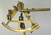
Among the earliest accessorial improvements
was optical enhancement of the image by means of a telescopic
attachment. Evidently this innovation came very near the advent of
the sextant itself, even though telescopes generally were not
incorporated for use with octants until about 1830. Strangely, a
similar such disparity was the use of a handle. Even the earliest
sextants had handles, whereas the inclusion of handles in the
construction of octants came at about the same time that optics were
added. Another feature unique to the sextant and lacking in the
octant was the scale/vernier magnifier. Because of its smaller size
and finer scale the sextant was read by means of a small magnifier
affixed to the index arm. The octant required none
|
|
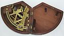
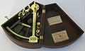
THE ULTIMATE EVOLUTION OF THE OCTANT
|
|
This lovely example signed "Parkinson & Frodsham,
London" also dates circa 1850. Note the addition of a handle
and horizon shades on the instrument itself. As for
accessories, a peep sight and telescopic sight have been
added. At this point, the only thing that differentiates the
octant from a sextant is the arc of its scale and lack of a
vernier magnifier. The existence of the "keystone" box helps
in pointing at its mid 19th C. or earlier origin. The trade
labels in the lid are those of Thaxter & Son and Aaron
Breed, both of Boston. Thaxter's were the American agents
for Parkinson & Frodsham during the first half of the
19th C. Original trade labels are an excellent tool in
helping to date the period of an instrument. (Collection
West Sea Co.)
|
By 1850 the demise of the octant was
imminent, even though its use persisted into the 20th century. The
superiority of the brass sextant in terms of accuracy, compactness,
and durability was indisputable.
The last half of the 19th century saw little
change in navigational instruments in general and the sextant in
particular. A good sextant would provide 50 years of service. As
makers fulfilled the need of mariners and demand declined there was
little incentive for improvement in manufacture or design.
With the onset of World War I and the loss
of hundreds of vessels and the construction of many more, nautical
instrument manufacture was given a second wind. The advent of the
drum micrometer sextant by the end of the War was the greatest single
improvement in the sextant during the 20th century. By employing a
continuous tangential screw attached to a calibrated knob, an
instantaneous reading visible in the low light situations of the
navigating bridge was readily obtainable. A further improvement was
the incorporation of a small battery powered light for easier
reading.
Actually this "new invention" was not new at
all. There is an example of the drum micrometer incorporated into a
sextant made by Ramsden that dates circa 1780. Before that it was
incorporated on some astronomical instruments dating back to the 17th
century!

|
|
MODERN SEXTANT
|
|
A post World War II Japanese sextant by "Tamaya, Ginza,
Tokyo." Modern features include a lightweight aluminum
frame, endless tangent screw drum micrometer read-out, a
built-in reading light, a large adjustable light gathering
telescope and over sized mirrors and filters. The triangular
device at the left is an artificial horizon, useful in low
light or foggy conditions. (Private Collection. Ex. West Sea
Co.)
|
Just prior to World War II the long
evolution of the sextant culminated in the invention of the ball
recording sextant. It is ironic, and perhaps fitting, that the final
form of the sextant was not a sextant at all but a much earlier
ancestor, the true quadrant. Developed for use at night when no
horizon was visible, the recording "sextant" used no reflecting
mirror. Rather, the celestial object was viewed directly as with the
true quadrant. Instead of using a plumb bob, a liquid-damped steel
ball recorded the altitude of the object on a screen. A drum
micrometer was used to determine the precise altitude reading.
Because of its size, easy reading, and nighttime capability, the
recording sextant found favor with airplane navigators, leading to
"aircraft sextants" built on the same principle. Numerous examples
still exist for the collector's choosing at relatively inexpensive
prices.
This has been a capsule look at the history
of the sextant, and in no way constitutes a thorough treatise on the
subject. Numerous topics relating to early navigation and its
instruments, including the nocturnal, traverse board, ring dial,
mariner's bow, circumferentor, hydrographic surveyor's sextant,
pocket or box sextant, and others have not been discussed. A selected
bibliography is provided to aid the reader in further study.
Good hunting!
Bibliography
Andrewes, William, "The Quest for Longitude
- Proceedings of the Longitude Symposium Harvard University November
1993," Harvard University, Cambridge, 1996.
Bedini, Silvio, "Early American Scientific
Instruments and Their Makers," Smithsonian Institution, Washington,
DC, 1964.
Bennett, J.A., "The Divided Circle," Phaidon
- Christie's, Oxford, 1987.
Brewington, M. V., "The Peabody Museum
Collection of Navigating Instruments," Peabody Museum, Salem,
1963.
Brophy, Patrick, "Sailing Ships," Galahad
Books, New York, 1974.
Clifton, Gloria, "Directory of British
Scientific Instrument Makers 1550-1851," The National Maritime
Museum, Greenwich, England, 1995.
Cotter, Charles H., "A History of the
Navigator's Sextant," Brown Son & Ferguson Ltd., Glasgow,
1983.
Gould, Rupert, "The Marine Chronometer," The
Holland Press, London, 1960.
Ifland, Peter, "Taking The Stars," The
Mariners' Museum, Newport News, 1998.
L'e Turner, Gerard, "Antique Scientific
Instruments," Blanford Press, London, 1980.
L'e Turner, Gerard, "Nineteenth Century
Scientific Instruments," Sotheby's Publications, London, 1983
Pearsall, Ronald, "Collecting and Restoring
Scientific Instruments," Arco Publishing Co., Inc., New York,
1974.
Randier, Jean, "Marine Navigation
Instruments," John Murray. London, 1980.
Stimson, Alan and Daniel, Christopher, "The
Cross Staff - Historical Development and Modern Use," Harriet Wynter,
London, 1977.
Taylor, E. G. R., and Richey, M. W., "The
Geometrical Seaman - A Book of Early Nautical Instruments," Hollis
and Carter, London, 1962.
Wheatland, David, "The Apparatus of Science
at Harvard 1765- 1800," Harvard University Press, Cambridge,
1968.
Wynter, Harriet and Turner, Anthony,
"Scientific Instruments," Charles Scribners Sons, New York,
1975
Significant events in the evolution of
angle measuring marine navigational instruments
Circa 9th century A.D.: First astronomical
quadrant
9th century A.D.: First astronomical
astrolabe. Brass and/or wood
10th century A.D.: Earliest surviving
example of astronomical astrolabe
11th century A.D. Directional properties of
lodestone employed
1187: Earliest known description of the
compass
1342: Cross staff described by Levi ben
Gerson
1415: Prince Henry the Navigator establishes
his navigation institute
Circa 1450: First recorded mention of the
mariner's simple quadrant, although the instrument predates this
period
Circa 1460: First mariner's astrolabe. Sheet
brass construction
Circa 1500: Introduction of cast brass
mariner's astrolabe
1555: Earliest surviving example of a dated
mariner's astrolabe
1594: Captain John Davis introduces
backstaff
1631: Pierre Vernier describes his method
for making an improved scale reading device
17th century: Backstaff constructed of
walnut, lignin vitae, and fruitwood. Non-interpolative linear
scale.
18th century: Backstaff constructed of
ebony, rosewood, and mahogany in addition to earlier materials.
Diagonal (interpolative) scale.
1731: John Hadley introduces reflecting
quadrant
1735: John Harrison's first
chronometer
1756: Mayer's reflecting circle
1757: First "Hadley sextant" by John
Bird.
1760: Brass, ebony and ivory introduced as materials for
constructing instrument frames. Brass begins replacing wood as the
preferred material, starting with the base of the index arm in
quadrants. Existing vernier scales calibrated "10 - 0 - 10"
1768: Scale dividing engine by Jesse
Ramsden
Circa 1770: Finite scale on vernier
calibrated "20 - 0 - 20".
Circa 1780: Instruments decrease in size
with widespread use of dividing engine in scale manufacture
Circa 1780: Introduction of vernier scale
with right reading "0."
Circa 1785: Inclusion of fine adjust tangent
screw feature in the production of most instruments. Index arm of
brass construction.
1788: Edward Troughton patents the
lightweight "pillar frame" sextant.
Circa 1790: Flat brass index arm gives way
to braced type.
Circa 1820: Elimination of backsight feature
in the construction of most octants
Circa 1840: Octants and sextants more
similar in appearance with the inclusion of handles, optics, and all
brass construction in octants
Circa 1880: Cessation of the production of
wooden instruments of the navigational type
Circa 1918: Inclusion of the drum micrometer
feature in modern sextants
Circa 1940: Ball recording sextant, aircraft
sextant
Characteristics of an octant or sextant
(as applicable) useful in dating
Dated instrument
Maker's name on instrument or box
label
Owner's name on instrument or box
Presence of backsight
Wooden index arm vs. brass combination wood
and brass index arm
Flat brass index arm vs. braced
Locking screw vs. locking screw and tangent
screw combination
Presence of vernier scale
Type of vernier scale division ("10 - 0 -
10" vs. "20 - 0 - 20" vs. "20 - 15 - 10 - 5 - 0")
Presence of vernier magnifier affixed to
index arm
Type of wood used in frame construction vs.
brass
Size of instrument
Frame configuration
Existence of index arm "stop" on right limb
of instrument
Use of ivory in some components
Presence of wooden "feet" vs. turned
brass
Presence of optics vs. peep
sights
Existence of pivoting peep sight
"shade"
Presence of an ivory "pencil" and/or
"notepad"
Presence of handle
Type of silvering used on mirrors
Configuration of box (angular shaped vs.
stepped keystone vs. keystone vs. rectangular wood vs.
bakelite)
Construction of box (type of dovetailing if
any)
Configuration of filter shades (double vs.
triple) and interchangeability of same
Existence of separate fixed horizon filters
in addition to index filters
Existence of variable height sighting tube
holder vs. earlier fixed holder
Information found on paper gasket inside
pivot point

© 1998-2013 West Sea Company. All rights
reserved. Reproducing any part of this article without the expressed
written consent of the author is forbidden by law. Violators will be
prosecuted.
